Best in Nation, United States Environmental Protection Agency
Loxahatchee River Environmental Control District (District) owns, operates, and maintains the regional wastewater treatment facility (WWTF) located on a 160-acre site in Jupiter, Florida. It serves the municipalities of Jupiter, Tequesta, Juno Beach, along with the unincorporated areas of northern Palm Beach County and southern Martin County. Domestic wastewater from residential and non-residential customers located within the District’s service boundaries is conveyed to the WWTF by the District’s wastewater collection system. The collection system consists of more than 1,575,660-feet (298-miles) of gravity sewer mains, 1,735 low pressure pump stations, 228 lift stations, approximately 554,046-feet (105-miles) of major wastewater force main piping and 154,501-feet (29-miles) of low pressure force main. The District also has 183,800-feet (35-miles) of I.Q. Water force mains.
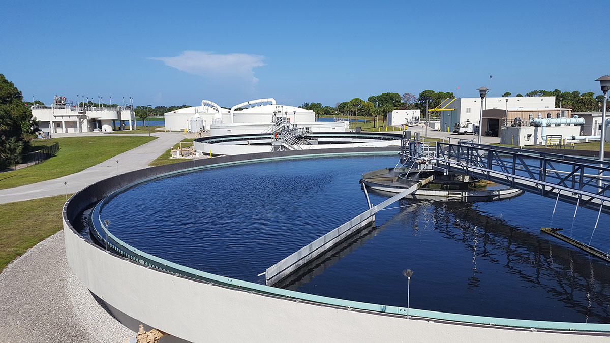
Secondary Clarifiers
Wastewater Treatment Facility Objectives
The objective of the District’s WWTF is to provide high level treatment of domestic wastewater collected from customers within the District’s service area with a central focus on protecting human health, safety, and welfare as well as to enhance the natural and built environmental systems of the Loxahatchee River Watershed.
To this end, the District has two methods of disposing of treated effluent:
- The primary method of effluent disposal is by treating all effluent to reclaimed water treatment standards (i.e., Irrigation Quality (IQ) Water) to meet landscape irrigation demands at local golf courses and throughout Abacoa. All IQ Water is required to meet the following criteria:
- Carbonaceous Biochemical Oxygen Demand (cBOD5): less than or equal to 20 milligrams per liter (mg/L) on annual average basis
- Total Suspended Solids (TSS): 5 mg/L, maximum
- pH: 6 to 8.5 standard units
- Chlorine Residual: 1 mg/L, minimum
The use of reclaimed water for irrigation purposes provides beneficial reuse of the treated effluent and significantly reduces the amount of groundwater withdrawn to meet landscape irrigation needs. Additionally, since IQ Water has higher concentrations of nitrogen and phosphorous than potable water there is typically a reduction in the amount of supplemental fertilizers applied by end users.
- The secondary method of effluent disposal at the District’s WWTF is by deep well injection. Treated effluent is disposed to the deep injection well during wet weather periods when IQ water demand is low or when there is no available storage capacity in the onsite IQ water equalization ponds or storage lakes. Treated effluent diverted to the deep injection well is required to meet the following criteria:
-
- Carbonaceous Biochemical Oxygen Demand (cBOD5): less than or equal to 20 mg/L on annual average basis
- Total Suspended Solids (TSS): less than or equal to 20 mg/L on annual average basis
- pH: 6 to 8.5 standard units
The injection of treated effluent to the deep injection well eliminates the discharge of nutrient rich water directly to surface waters and in particular the Loxahatchee River.
Current WWTF Process Systems
The District’s WWTF currently has a rated capacity of 11.0 million gallons per day (MGD) on an annual average daily flow (AADF) basis. At the present time, it is anticipated that the District’s service area is nearing build-out conditions. As such, expansion of the District’s WWTF in the near future is not anticipated. The WWTF processes include preliminary screening, influent flow equalization, aerobic activated sludge treatment, secondary clarification, tertiary filtration, and high-level disinfection using a concentrated chlorine solution. The WWTF is also equipped with an injection well pumping station, deep injection well, I.Q. Water pump station, and approximately 65 acres of lakes that store approximately 140 million gallons of I.Q. Water. The biosolids processing system includes storage, dewatering, offsite hauling, additional treatment (pelletization) and disposal. A detailed summary of the process systems currently in-service at the District’s WWTF is presented below.
- Preliminary Screening: Preliminary screening of the influent wastewater to the District’s WWTF is performed at the headworks structure. Raw wastewater is pumped from the collection system to the headworks structure where it is first routed to two (2) mechanical bar screen units. The primary purpose the screening units is to remove inorganic material (i.e. undissolved paper, plastics, etc.), which could clog and/or have detrimental impacts on the downstream treatment processes. The screening units have a screen opening size of 1/8-inch (3 millimeters, mm). All captured screenings are routed to a screenings washer-compactor unit where they are dewatered, and the captured solids are discharged to a dumpster for offsite disposal.
Screened water is then conveyed to a vortex type grit (i.e. sand) removal system. The vortex grit removal unit is designed to create a velocity gradient across the unit which allows the relatively heavier grit to settle to the bottom of the unit. Collected grit is conveyed by grit pumps to a grit classifier unit where it is dewatered and the captured grit is discharged to a dumpster for offsite disposal.
Once the influent wastewater passes through the grit removal unit it is routed through one of two Parshall Flume flow metering devices where it is subsequently conveyed by gravity to one of three aeration basins. During peak flow periods, excessive influent flow discharges over an overflow weir and is conveyed to one of two flow equalization tanks.
- Influent Flow Equalization: The District’s WWTF is equipped with influent (i.e. pre) flow equalization facilities which include two (2) 0.75 million gallon (MG) pre-stressed concrete storage tanks, three (3) equalization mixing pumps, a coarse bubble diffused aeration system including three (3) positive displacement blowers, and three (3) equalization return pumps. The purpose of the influent flow equalization facilities is to lower peak diurnal wastewater flow by temporarily storing a portion of the influent flow during peak hours and then returning the flow to the treatment process during non-peak hours. Utilizing influent flow equalization allows downstream processes to be sized for a lower flow than if influent flow equalization was not provided.
- Activated Sludge Treatment: Secondary treatment of the influent wastewater at the District’s WWTF is achieved utilizing a conventional activated sludge treatment process within three (3) cast-in-place concrete aeration basins. The main objective of the activated sludge treatment process is to promote and cultivate the growth of aerobic microorganisms which consume and reduce cBOD5 concentration in wastewater. Influent wastewater is mixed with return activated sludge (RAS) from the secondary clarifier units which is then aerated using a total of four (4) multi-stage centrifugal blowers and fine bubble diffusers to maintain appropriate dissolved oxygen concentration profiles across each of the in-service aeration basins. Mixing RAS with influent wastewater is required to maintain a mature and healthy population of microorganisms within the aeration basins. Failure to maintain a healthy mass of microorganisms, as determined by the mixed liquor suspended solids (MLSS) concentration in the aeration basins, can result in inadequate treatment. Periodic disposal of waste activated sludge (WAS) is also critical to maintaining an appropriate sludge age and MLSS concentration. As activated sludge ages it becomes less efficient at reducing cBOD5 concentrations due to decreasing metabolic efficiency. To maintain a desirable sludge age, the WWTF Operations staff routinely monitors and evaluates the solids retention time (SRT) and food to microorganism (F/M) ratio.
- Secondary Clarification: MLSS from each aeration basin flows by gravity to one of four secondary clarifier units. Secondary clarifiers are settling basins which are sized and configured to promote the gravity sedimentation of activated sludge to the base of the clarifier unit. Influent flow enters through a vertical riser pipe in the center column at each clarifier unit and is discharged into a circular inlet well. The inlet well dissipates energy from the influent flow and directs it radially outward. As the flow travels outward from the center, suspended solids settle to the bottom and clarified secondary effluent discharges over a circumferential weir. Settled solids are directed to the center of the clarifier unit by a rotating scraper mechanism at the base of the clarifier where they are either returned to the aeration basins by RAS pumps or pumped to the sludge storage tank by the WAS pumps for eventual biosolids processing and offsite disposal.
- Tertiary Filtration: Clarified secondary effluent from the clarifier units is pumped by one of two Filter Pump Stations (No. 1 and 2) to the inlet of either the Deep Bed Filter Units or Synthetic Media Filters. The primary objective of the tertiary filtration units is to further reduce the TSS concentration in the secondary clarifier effluent. Filtration removes fine organic and inorganic materials, including particulate cBOD5 and insoluble phosphorous. Suspended solids are captured between the media particles or are deposited on the surface of the individual media particles. As the filter operates solid particles accumulate within the media bed and clog the pore space which results in increased head (i.e. pressure) loss across the filter units. This head loss causes the water level in the filter units to rise. In order to clean the filter units and reduce the water level in the filters to their normal operating levels, the filter units are periodically backwashed using filtered water and an air scour process which is induced by two (2) process air blowers.
- Chlorine Disinfection System: Filter effluent is conveyed by gravity through a Parshall Flume metering device and subsequently to one of two chlorine contact chambers. Each of the chlorine contact chambers was constructed with baffle walls which are intended to increase the contact time between the filtered effluent and the applied chlorine disinfectant. The District currently uses chlorine for disinfection purposes. A highly concentrated chlorine solution is injected at the inlet of each of the chlorine contact chambers. Chlorine is known to be the most effective disinfectant available. Once chlorinated at the required dose for the prescribed time, filter effluent is considered to be Irrigation Quality (IQ) Water since it meets all reclaimed water regulatory requirements specified by the Florida Department of Environmental Protection.
- IQ Water Storage and Distribution: Following disinfection, IQ Water is discharged to IQ storage pond/lakes located at the WWTF site. Flow is initially diverted to one of two lined stabilization ponds which each have an approximate storage volume of 9.5 MG, for a total approximate storage volume of 19.0 MG. Once the water level in the storage ponds reaches its maximum operating level, IQ Water flows to a control structure where it is diverted to four (4) onsite storage lakes which have varying storage capacities. The cumulative storage volume of the storage lakes is approximately 118.5 MG. Based on this, the total combined storage capacity of the stabilization ponds and lakes is approximately 137.5 MG
IQ water is pumped offsite using one of two IQ water pumping stations. IQ-511 is the primary reclaimed water distribution pump station which conveys IQ water to twelve (12) offsite reclaimed water application sites. IQ-512 conveys reclaimed water to the western service area which includes one (1) offsite reclaimed water application site. IQ water is generally pumped from the WWTF and discharged into offsite IQ storage lakes. IQ water is then applied, as needed, by dedicated irrigation pump stations located at each of the offsite storage lakes. The offsite storage lakes and associated irrigation pump stations are owned, operated, and maintained by the respective reclaimed water application site owners. The District owns, operates, and maintains one offsite pumping station (IQ-518) which distributes IQ water to specific application sites within the Abacoa Community including Roger Dean Stadium. The District does not own, operate or maintain the offsite lakes within the Abacoa community.
- Injection Well Pump Station and Deep Injection Well: During prolonged wet weather periods when IQ Water demand is low or when the onsite storage lakes are at capacity, secondary effluent is diverted to the injection well system. Effluent from the secondary clarifier units is diverted, through Filter Pump Station No. 1, to the injection well screening structure. The screening structure is partitioned into two (2) compartments which are both equipped with manual bar racks which have ¼-inch (6mm) openings. Once screened, secondary effluent flows to one of two injection well pump station wet wells where it is pumped to the deep injection well for disposal. The injection zone of the deep injection well is approximately 2,839 to 3,500-ft below grade. This injection zone is directly below the lower Floridan Aquifer confining layer which extends approximately 650-ft below the lower limits of the Floridan Aquifer system.
- Biosolids Handling and Processing Facilities: Biosolids management is a critical function at all wastewater treatment facilities. In order to maintain a healthy biomass, sludge age and MLSS concentration, waste activated sludge needs to be removed from the secondary treatment process on a daily basis. At the District’s WWTF, WAS is pumped from the bottom of each of the secondary clarifier units to a 0.5 MG sludge storage tank. The sludge storage tank is equipped with two (2) process air blowers and a fine bubble diffused aeration system. Aeration of the tank contents prevents the WAS from becoming septic, reduces the formation of foul odors and conditions the sludge prior to dewatering. WAS is pumped from the sludge storage tank to one of two belt filter press units where it is dewatered, with the addition of a polymer, to a concentration of 14 to 16% solids. Dewatered sludge (which is then termed “biosolids”) is loaded into tractor trailers where it is hauled offsite to the Solid Waste Authority Biosolids Processing Facility. Biosolids are then heat dried and converted to pellets which are utilized as a fertilizer supplement or alternate energy fuel source. For more information, see https://swa.org/Facilities/Facility/Details/Biosolids-Processing-Facility-20.
Loxahatchee River District has been a leader in wastewater collection, treatment and management since its founding in 1971. As a progressive utility, the District is continually looking for ways to implement modern technologies and approaches to improve treatment, increase operational efficiency, and to be a leader in environmental stewardship. The District has been awarded numerous Awards for Excellence in wastewater treatment including:
- Florida Engineering Society
- Florida Department of Environmental Protection – “Earle B. Phelps” Award
- Florida Water Environment Association – “David W. York Award”, and
- Environmental Protection Agency’s highest honor – “Best in Nation” Award
Historical Progression of the District’s WWTF Process
The District’s WWTF was originally placed into operation in 1975 as an advanced wastewater treatment (AWT) facility with an AADF of 4.0 MGD. The original treatment process used high rate pure oxygen produced by two (2) pressure swing adsorption (PSA) oxygen generators to perform aerobic reduction of cBOD5 in the influent, raw wastewater stream. This process was followed by secondary clarification, tertiary clarification, tertiary filtration, and disinfection of the secondary effluent using a concentrated solution of chlorine. Treated effluent was conveyed and discharged to a recharge pond located approximately 4-miles west of the current WWTF site and ultimately into the Northwest Fork of the Loxahatchee River.
In the early 1980’s, it became evident to the District that specific upgrades and improvements to the WWTF processes were warranted to mitigate potential long term impacts associated with discharge of nutrient (nitrogen and phosphorous) rich secondary effluent into the Loxahatchee River. Recognizing that treated effluent was a valuable resource (as reclaimed or reuse water), the District developed and implemented two alternate disposal options which remain standard practice today: reuse of treated effluent as IQ Water and deep well injection. Production of IQ water is the primary disposal option, but the deep injection well is maintained as a backup in order to meet regulatory reliability standards. To implement the two methods of beneficial reuse the District designed and constructed a deep injection well, traveling bridge tertiary filters, IQ distribution pump station, and IQ transmission mains over the course of several years in the mid 1980’s. Upon completion of these upgrades the WWTF capacity was subsequently re-rated to 8.0 MGD, on an AADF basis, since the original AWT effluent requirements were more restrictive then the IQ water treatment standards.
Biosolids dewatering and lime stabilization facilities were constructed at the WWTF in the late 1980’s. Biosolids treatment facilities were installed to increase the quality and reduce the volume of biosolids requiring disposal, which were land applied for agricultural purposes. Prior to this time, waste biosolids were either land applied wet or disposed of at an approved landfill site.
A new headworks structure was constructed as part of facility improvements in 1991 and the traveling bridge tertiary filter treatment process was expanded from four (4) units to six (6) units in 1994. The WWTF capacity was subsequently re-rated to 9.0 MGD, on an AADF basis, in 1999.
The WWTF was expanded to its current rated capacity of 11.0 MGD, on an AADF basis, in 2007. This expansion included the replacement and/or installation of critical equipment and process components including:
- Influent flow equalization facilities including two (2) 0.75 MG pre-stressed concrete storage tanks, three (3) equalization mixing pumps, a coarse bubble diffused aeration system including three (3) positive displacement blowers, and three (3) equalization return pumps which convey equalized flow to the aeration basins
- Replacement of the high rate pure oxygen process with fine bubble diffused aeration which included the construction of three (3) aeration basins, centrifugal process air blowers, process air piping and a dissolved oxygen control scheme
- The rehabilitation of three (3) existing secondary clarifier units as well as the construction of a fourth unit
- Construction of a second filter dosing pump station and new synthetic media filter units with a design hydraulic treatment capacity of 8.0 MGD
- Replacement and upgrade of chlorine disinfectant storage and feed facilities, as well as the construction of two (2) new chlorine contact chambers
- Construction of a new 0.5 MG pre-stressed concrete WAS storage tank
- Replacement of the two (2) primary, back-up/emergency generator units
The most recent WWTF improvements project was completed in 2018 and included specific upgrades to the tertiary filtration system to increase system reliability and resiliency. The existing traveling bridge filters were approximately forty years old and had reached the end of their useful life. The project was also designed to ensure that the District would be well positioned to meet future environmental regulations which are anticipated to require increased nutrient removal, specifically nitrogen. The project included the decommissioning and replacement of the traveling bridge filters with deep bed sand media filtration units which are also capable of denitrification. Denitrification in the deep bed filters will require the introduction of a liquid carbon source at the influent to the filters to drive the process.
The upgrades in the Deep Bed Filter Unit project included:
- Replacement of the mechanical systems at Filter Pump Station No. 1 including pumps, piping, valving and miscellaneous equipment
- New electrical building to service the new Deep Filter Units, and to interconnect the electrical systems at Electrical Building No’s 1 and 3 as well as the Blower Building. The electrical interconnect allows critical plant processes and equipment to be serviced by either one of the two (2) primary back-up/emergency generator units.
- Installation of a Parshall Flume flow metering device at the inlet of the two (2) existing chlorine contact chambers, downstream of the Deep Bed Filter Units
Author: Jason A. Pugsley, P.E., LRD Operations Plant Manager
Last Edited: August 31, 2020